Circuit wiring
Overview
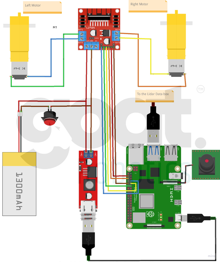
This document provides a comprehensive explanation of the wiring diagram for the Jarvis Bot, a mini Autonomous Mobile Robot (AMR) designed for educational purposes. The diagram illustrates the connections between various components, including the Raspberry Pi, motor driver, DC motors, Li-Po battery, Lidar data box, push button, and HDMI cable.
Component Breakdown
- Raspberry Pi: The central processing unit of the robot, responsible for controlling the overall operation, processing data from sensors, and making decisions based on the information received.
- L298N Motor Driver: A bridge driver that controls the speed and direction of the DC motors. It receives commands from the Raspberry Pi and translates them into electrical signals to drive the motors.
- DC Motors: The actuators that power the wheels of the robot. They convert electrical energy into mechanical energy to propel the robot forward, backward, or turn.
- Li-Po Battery: A rechargeable battery that provides power to the entire system. It is typically chosen for its high energy density and lightweight design.
- Lidar Data Box: A device that processes data from a LiDAR (Light Detection and Ranging) sensor. LiDAR sensors emit laser beams and measure the time it takes for the beams to return, allowing the robot to determine the distance to objects in its environment.
- Push Button: A simple input device that can be used to trigger specific actions or commands. It can be used for manual control, emergency stops, or other functions.
- HDMI Cable: Connects the Raspberry Pi to a monitor or display, allowing the user to visualize the robot's status, sensor data, and control interface.
Wiring Connections
- Raspberry Pi to L298N Motor Driver: The Raspberry Pi is connected to the L298N motor driver using GPIO (General-Purpose Input/Output) pins. The Raspberry Pi sends control signals to the motor driver, which in turn controls the DC motors.
- L298N Motor Driver to DC Motors: The L298N motor driver is connected to the DC motors using wires. The motor driver provides the necessary power and control signals to the motors.
- Li-Po Battery to System: The Li-Po battery is connected to the power input of the L298N motor driver and the Raspberry Pi. It provides the main source of power for the entire system.
- Lidar Data Box to Raspberry Pi: The Lidar data box is connected to the Raspberry Pi using a serial communication interface (e.g., I2C or UART). The data box sends sensor data to the Raspberry Pi for processing.
- Push Button to Raspberry Pi: The push button is connected to a GPIO pin on the Raspberry Pi. When the button is pressed, it generates a signal that can be detected by the Raspberry Pi.
- HDMI Cable to Raspberry Pi: The HDMI cable connects the Raspberry Pi to a monitor or display. This allows the user to view the output of the Raspberry Pi, including the robot's status, sensor data, and control interface.
Additional Considerations
- Power Supply: Ensure that the Li-Po battery is rated for the appropriate voltage and current requirements of the system.
- Motor Control: The L298N motor driver may require additional components or configuration settings to achieve precise control of the DC motors.
- Sensor Integration: The Lidar data box may need to be calibrated and configured to work properly with the Raspberry Pi and the robot's specific requirements.
- Software Development: The Raspberry Pi will require appropriate software to process sensor data, control the motors, and implement the desired functionality.
By understanding the wiring diagram and the components involved, you can effectively assemble, configure, and operate the Jarvis Bot. This document provides a solid foundation for further exploration and customization of the robot's capabilities.